| Input Voltage Range | 90 Vac ~264Vac |
| Rated Input Voltage | 100 Vac ~240Vac |
| Input Frequency Range | 47HZ~63HZ |
| Rated Frequency Range | 50HZ~60HZ |
| Input Current | Max. 3.5A at100Vac input and full load Max. 2.5A at 240Vac input and full load |
| Inrush current | ≤80A at 230Vac |
| Power Factor | ≥0.95 at 230Vac (Load test) |
| Efficiency | Efficiency should at 100% load >86.0% at 100Vac Efficiency should at 100% load >89.0% at 230Vac |
| Item | Remark |
| Short Circuit Protection | Hiccup, troubleshooting conditions, the power output is restored. |
| Item | Over Current | Remark |
| Over Current Protection | 120% ~ 160% | OCP trigger point must be between 120% and 160% of rated load current. Power supply output must recover automatically with normal load when the fault condition is removed. |
| Item | Under Voltage | Remark |
| Input Under Voltage Protection | 70Vac to 89Vac | No output power protection(0%-100% LOAD). |
| Item | Recovery | Remark |
| Input Under Voltage Recovery | 88Vac to 90Vac | Output recovery. (0%-100%LOAD). |
| Operation Temperature | -10℃ to +70℃(-30°C can start up) |
| Storage Temperature | -40℃ to +85℃ |
| Operating Relative Humidity | 5%RH to 90%RH |
| Storage Relative Humidity | 5%RH to 95%RH |
| Operating Altitude | ≦2000m |
| Storage Altitude | ≦2000m |
| Climates | Apply to the tropical climate |
| Cooling Method | Natural cooling |
Ambient Temperature and Output Current
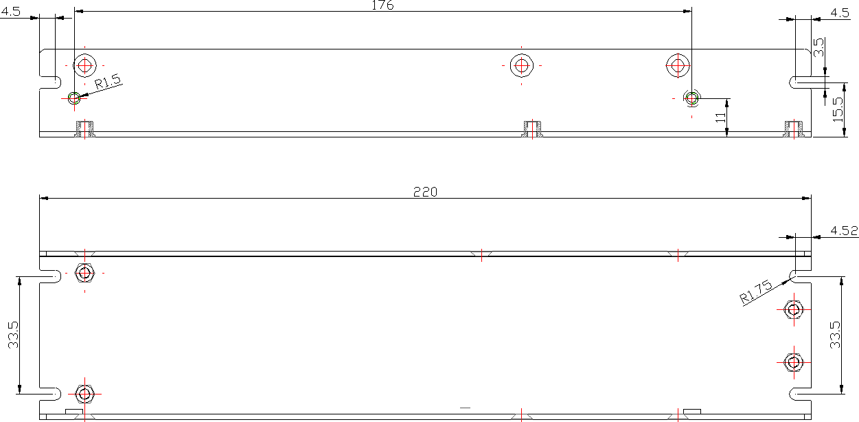
| Dimensions | Dimensions: 220mmx48mmx26mm±0.5mm |
 CN01(Type: 8.25mm,3Pin)
 | Pin number | Symbol | Function |
| 1 | L | AC Input L |
| 2 | N | AC Input N |
| 3 | G | Ground |
| Pin number | Symbol | Function |
| 4 | V- | DC Output - |
| 5 | V- | DC Output - |
| 6 | V+ | DC Output + |
| 7 | V+ | DC Output + |
| Output Power | 300W |
| Output Channel | CON2(+)(-) |
| Rated Output Voltage | +5.0V Vdc |
| Voltage accuracy | 2% |
| Rated Current | 100Vac to 180Vac/50A 180Vac to 240Vac/60A |
| Output Channel | Rated Output Voltage | Output Ripple & Noise |
| 100Vac to180Vac(50A)180Vac to240Vac(60A) | ||
| CON2(+)(-) | +5.0 Vdc | ≤300mV |
- the Bandwidth of oscilloscope is set to 20MHz.
- On the output side lock 10 cm cable to a 0.1uF ceramic capacitors in parallel and a 10uF electrolytic capacitor to test the ripple and noise.
| Output Channel | Rated Output Voltage | Turn on Delay Time |
| 100Vac to180Vac(50A) 180Vac to240Vac(60A) | ||
| CON1(+)(-) | +5.0Vdc | ≤3S |
| Output Channel | Rated Output Voltage | Hold up Time |
| 100Vac to180Vac(50A) 180Vac to240Vac(60A) | ||
| CON1(+)(-) | +5.0 | ≥5mS |
| Output Channel | Rated Output Voltage | Output Voltage Rise Time |
| 100Vac to180Vac(50A) 180Vac to240Vac(60A) | ||
| CON2(+)(-) | +5.0 | ≦100mS |
| Output Channel | Rated Output Voltage | Output Overshoot |
| 100Vac to180Vac(50A) 180Vac to240Vac(60A) | ||
| CON2(+)(-) | +5.0 Vdc | ≦10% |
| Output Channel | Rated Output Voltage | Transient Response |
| 100Vac to180Vac(50A) 180Vac to240Vac(60A) | ||
| CON2(+)(-) | +5.0 Vdc | Output:0-50%,50%~100% Slew Rate:1A/uS, The output overshoot and undershoot should be ≤±10% of Transient Response Recovery Time:200us |
| NO. | Item | Remark |
| 5.1 | Power On/off Cycle | Products at room temperature environment, Rated input and output, switch the 3 s 1000 times the frequency of the cycle. |
| 5.2 | Burn-In Test | Products in 40℃ environment, input 220Vac, output rated load operation 72 hours continuously. |
| 5.3 | Vibration | IEC60068-2-6, Sine wave excited, acceleration 10Hz~150Hz at 25M/S2 2.5g peak; 90min per axis for all X, Y, Z direction. IEC60068-2-6, Random: 5Hz–500Hz at 2.09G RMS peak. 20 min per axis for all X,Y,Z direction |
| 5.4 | Shock | 49m/s²(5G),11ms, once each X, Y and Z axis |
| 5.5 | MTBF | The Calculated MTBF should be more than 20,000 hours as per Telcordia SR-332 when AC 220V/50Hz and full load output at |
| 5.6 | Electrolytic Capacitor Life | The Calculated capacitor life shall be more 10 years when AC 220V/50Hz input, 50% load at 35°C ambient. |
| NO. | Item | Condition | Remark | |
| 6.1 | Dielectric Strength | Primary to Secondary | 3000Vac, 5mA, 60S | No flying arc and no breakdown |
| Primary to Ground | 1500Vac, 5mA, 60S | |||
| Secondary to Ground | 500Vac, 5mA, 60S | |||
| 6.2 | Insulation Resistance | Primary to Secondary | 500Vdc, ≥10MΩ | Under normal atmospheric pressure, relative humidity of 90%, test DC voltage 500V |
| Primary to Ground | ||||
| Secondary to Ground | ||||
| 6.3 | Leakage Current | Primary to Secondary | ≤5.0mA | Class I |
| 6.4 | Ground Impedance | <0.1 ohms. | 32A/2 minutes(UL Certified model: 40A/2 minutes) | |
| 6.5 | Safety Certification | / |
| |

Input voltage and Output Current
 Remark:
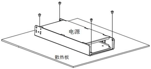
 - Recommend that the Power Supply should be mounted tightly with the heat sink described.(Heat sink size:250*250*3mm)
- The power supply cannot be used under the environment of more than 264Vac.
In order to conform to the ambient temperature and output current drop curve and input voltage and output current drop curve power supply must be installed on an aluminum plate, it is suggested that the size of the aluminum plate is shown in the following figure. To optimize heat dissipation, aluminum surface must be smooth.
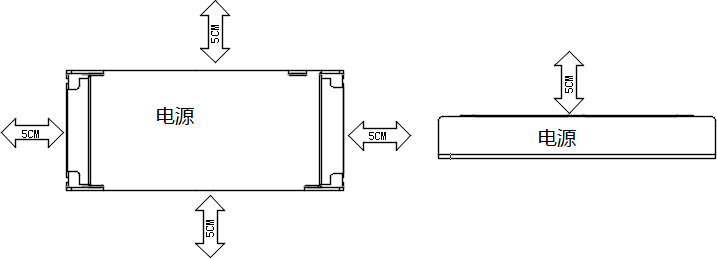
 To ensure good heat dissipation, at least 5cm of space around the power supply must be reserved during installation, as shown in the figure below
