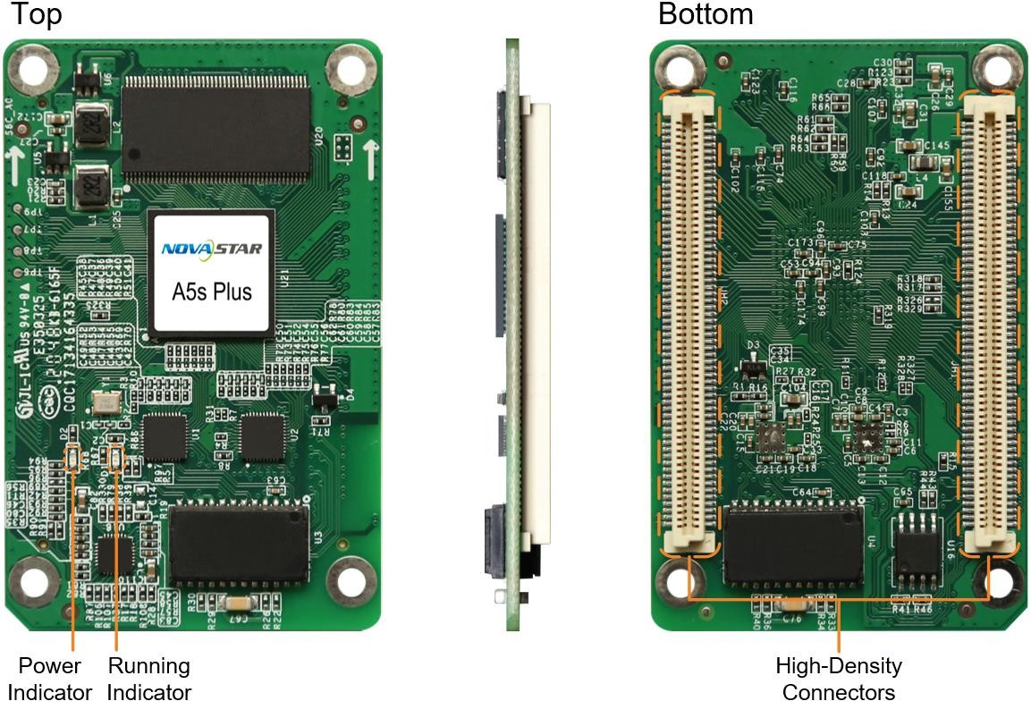
 All product pictures shown in this document are for illustration purpose only. Actual product may vary.
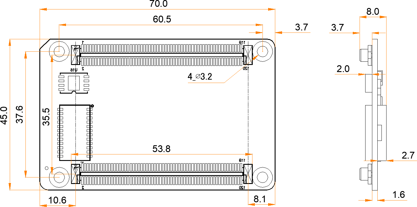
 The A5s Plus is a general small receiving card developed by Xi’an NovaStar Tech Co., Ltd. (hereinafter referred to as NovaStar). A single A5s Plus supports resolutions up to 512×384@60Hz (NovaLCT V5.3.1 or later required). Supporting color management, 18bit+, pixel level brightness and chroma calibration, individual gamma adjustment for RGB, and 3D functions, the A5s Plus can significantly improve the display effect and user experience. The A5s Plus uses high-density connectors for communication to limit the effects of dust and vibration, resulting in high stability. It supports up to 32 groups of parallel RGB data or 64 groups of serial data (expandable to 128 groups of serial data). Its reserved pins allow for custom functions of users. Thanks to its EMC Class B compliant hardware design, the A5s Plus has improved electromagnetic compatibility and is suitable for various on-site setups.RoHS, EMC Class BThe distance between outer surfaces of the A5s Plus and hub boards after their high-density connectors fit together is 5.0 mm. A 5-mm copper pillar is recommended. To make molds or trepan mounting holes, please contact NovaStar for a higher-precision structural drawing.
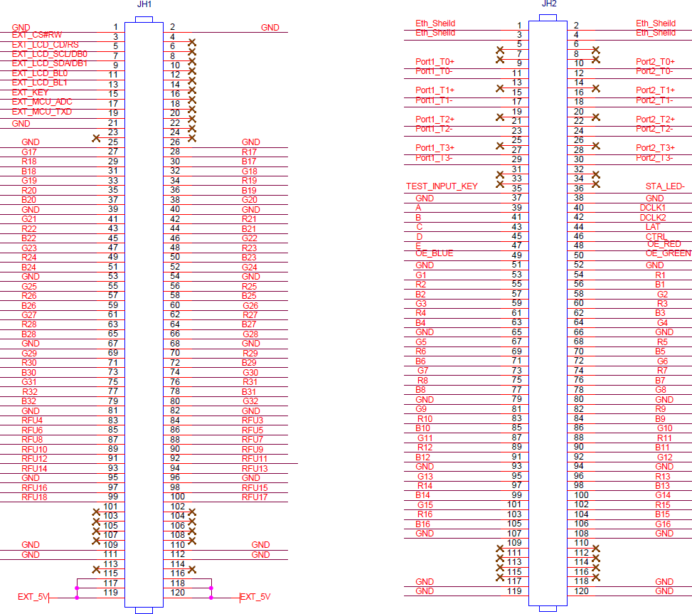
| JH2 | |||||
| NC | 25 | 26 | NC | ||
| Port1_T3+ | 27 | 28 | Port2_T3+ | ||
| Port1_T3- | 29 | 30 | Port2_T3- | ||
| NC | 31 | 32 | NC | ||
| NC | 33 | 34 | NC | ||
| Test button | TEST_INPUT_KEY | 35 | 36 | STA_LED- | Running indicator (active low) |
| GND | 37 | 38 | GND | ||
| Line decoding signal | A | 39 | 40 | DCLK1 | Shift clock output 1 |
| Line decoding signal | B | 41 | 42 | DCLK2 | Shift clock output 2 |
| Line decoding signal | C | 43 | 44 | LAT | Latch signal output |
| Line decoding signal | D | 45 | 46 | CTRL | Afterglow control signal |
| Line decoding signal | E | 47 | 48 | OE_RED | Display enable signal |
| Display enable signal | OE_BLUE | 49 | 50 | OE_GREEN | Display enable signal |
| GND | 51 | 52 | GND | ||
| / | G1 | 53 | 54 | R1 | / |
| / | R2 | 55 | 56 | B1 | / |
| / | B2 | 57 | 58 | G2 | / |
| / | G3 | 59 | 60 | R3 | / |
| / | R4 | 61 | 62 | B3 | / |
| / | B4 | 63 | 64 | G4 | / |
| GND | 65 | 66 | GND | ||
| / | G5 | 67 | 68 | R5 | / |
| / | R6 | 69 | 70 | B5 | / |
| / | B6 | 71 | 72 | G6 | / |
| / | G7 | 73 | 74 | R7 | / |
| / | R8 | 75 | 76 | B7 | / |
| / | B8 | 77 | 78 | G8 | / |
| GND | 79 | 80 | GND | ||
| / | G9 | 81 | 82 | R9 | / |
| / | R10 | 83 | 84 | B9 | / |
| / | B10 | 85 | 86 | G10 | / |
| / | G11 | 87 | 88 | R11 | / |
| / | R12 | 89 | 90 | B11 | / |
| / | B12 | 91 | 92 | G12 | / |
| GND | 93 | 94 | GND | ||
| / | G13 | 95 | 96 | R13 | / |
| / | R14 | 97 | 98 | B13 | / |
| / | B14 | 99 | 100 | G14 | / |
| / | G15 | 101 | 102 | R15 | / |
| / | R16 | 103 | 104 | B15 | / |
| / | B16 | 105 | 106 | G16 | / |
| GND | 107 | 108 | GND | ||
| NC | 109 | 110 | NC | ||
| NC | 111 | 112 | NC | ||
| NC | 113 | 114 | NC | ||
| NC | 115 | 116 | NC | ||
| GND | 117 | 118 | GND | ||
| GND | 119 | 120 | GND | ||
⬤Quick uploading of calibration coefficients The calibration coefficients can be quickly uploaded to the receiving card, improving efficiency greatly.
⬤Module Flash management
For modules with flash memory, the information stored in the memory can be managed. The calibration coefficients and module ID can be stored and read back. ⬤One click to apply calibration coefficients in module Flash For modules with flash memory, when the Ethernet cable is disconnected, users can hold down the self-test button on the cabinet to upload the calibration coefficients in the flash memory of the module to the receiving card. ⬤Mapping function The cabinets display the receiving card number and Ethernet port information, allowing users to easily obtain the locations and connection topology of receiving cards. ⬤Setting of a pre-stored image in receiving card The image displayed during startup, or displayed when the Ethernet cable is disconnected or there is no video signal can be customized. ⬤Temperature and voltage monitoring The temperature and voltage of the receiving card can be monitored without using peripherals. ⬤Cabinet LCD The LCD module connected to the cabinet can display the temperature, voltage, single run time and total run time of the receiving card ⬤Bit error detection The Ethernet port communication quality of the receiving card can be monitored and the number of erroneous packets can be recorded to help troubleshoot network communication problems. NovaLCT V5.2.0 or later is required. ⬤Status detection of dual power supplies When two power supplies are used, their working status can be detected by the receiving card. ⬤Firmware program readback The firmware program of the receiving card can be read back and saved to the local computer.NovaLCT V5.2.0 or later is required.
l Configuration parameter readback
The configuration parameters of the receiving card can be read back and saved to the local computer.
⬤LVDS transmission (dedicated firmware required) Low-voltage differential signaling (LVDS) transmission is used to reduce the number of data cables from the hub board to module, increase the transmission distance, and improve the signal transmission quality and electromagnetic compatibility (EMC). ⬤Dual card backup and status monitoring In an application with requirements for high reliability, two receiving cards can be mounted onto a single hub board for backup. When the primary receiving card fails, the backup card can serve immediately to ensure uninterrupted operation of the display.The working status of the primary and backup receiving cards can be monitored in NovaLCT V5.2.0 or later.
⬤Loop backup
The receiving cards and the sending card form a loop via the primary and backup line connections. When a fault occurs at a location of the lines, the screen can still display the image normally.⬤Dual backup of configuration parameters The receiving card configuration parameters are stored in the application area and factory area of the receiving card at the same time. Users usually use the configuration parameters in the application area. If necessary, users can restore the configuration parameters in the factory area to the application area. ⬤Dual program backup Two copies of firmware program are stored in the application area of the receiving card at the factory to avoid the problem that the receiving card may get stuck abnormally during program update.| Pins for Extended Functions | |||
| Pin | Recommended Module Flash Pin | Recommended Smart Module Pin | Description |
| RFU4 | HUB_SPI_CLK | Reserved | Clock signal of serial pin |
| RFU6 | HUB_SPI_CS | Reserved | CS signal of serial pin |
| RFU8 | HUB_SPI_MOSI | / | Module Flash data storage input |
| / | HUB_UART_TX | Smart module TX signal | |
| RFU10 | HUB_SPI_MISO | / | Module Flash data storage output |
| / | HUB_UART_RX | Smart module RX signal | |
| RFU3 | HUB_CODE0 | Module Flash BUS control pin | |
| RFU5 | HUB_CODE1 | ||
| RFU7 | HUB_CODE2 | ||
| RFU9 | HUB_CODE3 | ||
| RFU18 | HUB_CODE4 | ||
| RFU11 | HUB_H164_CSD | 74HC164 data signal | |
| RFU13 | HUB_H164_CLK | ||
| RFU14 | POWER_STA1 | Dual power supply detection signal | |
| RFU16 | POWER_STA2 | ||
| RFU15 | MS_DATA | Dual card backup connection signal | |
| RFU17 | MS_ID | Dual card backup identifier signal | |
| Indicator | Color | Status | Description |
| Running indicator | Green | Flashing once every 1s | The receiving card is functioning normally. Ethernet cable connection is normal, and video source input is available. |
| Flashing once every 3s | Ethernet cable connection is abnormal. | ||
| Flashing 3 times every 0.5s | Ethernet cable connection is normal, but no video source input is available. | ||
| Flashing once every 0.2s | The receiving card failed to load the program in the application area and is now using the backup program. | ||
| Flashing 8 times every 0.5s | A redundancy switchover occurred on the Ethernet port and the loop backup has taken effect. | ||
| Power indicator | Red | Always on | The power input is normal. |


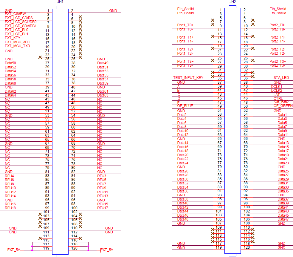
| JH2 | |||||
| NC | 25 | 26 | NC | ||
| Port1_T3+ | 27 | 28 | Port2_T3+ | ||
| Port1_T3- | 29 | 30 | Port2_T3- | ||
| NC | 31 | 32 | NC | ||
| NC | 33 | 34 | NC | ||
| Test button | TEST_INPUT_KEY | 35 | 36 | STA_LED- | Running indicator (active low) |
| GND | 37 | 38 | GND | ||
| Line decoding signal | A | 39 | 40 | DCLK1 | Shift clock output 1 |
| Line decoding signal | B | 41 | 42 | DCLK2 | Shift clock output 2 |
| Line decoding signal | C | 43 | 44 | LAT | Latch signal output |
| Line decoding signal | D | 45 | 46 | CTRL | Afterglow control signal |
| Line decoding signal | E | 47 | 48 | OE_RED | Display enable signal |
| Display enable signal | OE_BLUE | 49 | 50 | OE_GREEN | Display enable signal |
| GND | 51 | 52 | GND | ||
| / | G1 | 53 | 54 | R1 | / |
| / | R2 | 55 | 56 | B1 | / |
| / | B2 | 57 | 58 | G2 | / |
| / | G3 | 59 | 60 | R3 | / |
| / | R4 | 61 | 62 | B3 | / |
| / | B4 | 63 | 64 | G4 | / |
| GND | 65 | 66 | GND | ||
| / | G5 | 67 | 68 | R5 | / |
| / | R6 | 69 | 70 | B5 | / |
| / | B6 | 71 | 72 | G6 | / |
| / | G7 | 73 | 74 | R7 | / |
| / | R8 | 75 | 76 | B7 | / |
| / | B8 | 77 | 78 | G8 | / |
| GND | 79 | 80 | GND | ||
| / | G9 | 81 | 82 | R9 | / |
| / | R10 | 83 | 84 | B9 | / |
| / | B10 | 85 | 86 | G10 | / |
| / | G11 | 87 | 88 | R11 | / |
| / | R12 | 89 | 90 | B11 | / |
| / | B12 | 91 | 92 | G12 | / |
| GND | 93 | 94 | GND | ||
| / | G13 | 95 | 96 | R13 | / |
| / | R14 | 97 | 98 | B13 | / |
| / | B14 | 99 | 100 | G14 | / |
| / | G15 | 101 | 102 | R15 | / |
| / | R16 | 103 | 104 | B15 | / |
| / | B16 | 105 | 106 | G16 | / |
| GND | 107 | 108 | GND | ||
| NC | 109 | 110 | NC | ||
| NC | 111 | 112 | NC | ||
| NC | 113 | 114 | NC | ||
| NC | 115 | 116 | NC | ||
| GND | 117 | 118 | GND | ||
| GND | 119 | 120 | GND | ||
| Maximum Resolution | 512×384@60Hz | |
| Electrical Parameters | Input voltage | DC 3.8 V to 5.5 V |
| Rated current | 0.6 A | |
| Rated power consumption | 3.0 W | |
| Operating Environment | Temperature | –20°C to +70°C |
| Humidity | 10% RH to 90% RH, non-condensing | |
| Storage Environment | Temperature | –25°C to +125°C |
| Humidity | 0% RH to 95% RH, non-condensing | |
| Physical Specifications | Dimensions | 70.0 mm × 45.0 mm × 8.0 mm |
| Net weight | 16.2 g Note: It is the weight of a single receiving card only. | |
| Packing Information | Packing specifications | Each receiving card is packaged in a blister pack. Each packing box contains 80 receiving cards. |
| Packing box dimensions | 378.0 mm × 190.0 mm × 120.0 mm | |
