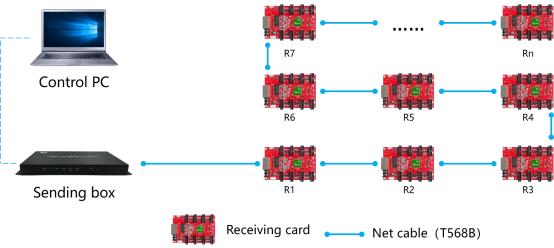
 Connection diagram of connecting R712 with display player box:
| With sending card | Dual-mode sending box ,Asynchronous sending card,Synchronous sending card, Video processor of VP series. |
| Module type | Compatible,with,all,common,IC,module,supported most PWM IC module. |
| Scan mode | Supports any scanning method from static to 1/64 scan |
| Communication method | Gigabit Ethernet |
| Control range | Recommend:65,536 pixels (128*512) Outdoor module width ≤256, Indoor module width ≤128 |
| Multi-card connection | Receiving card can be put in any sequence |
| Gray scale | 256~65536 |
| Smart setting | A few simple steps to complete the smart settings, through the screen layout can be set to go with any alignment of the screen unit board. |
| Test functions | Receiving card integrated screen test function, Test display brightness uniformity and display module flatness. |
| Communication distance | Super Cat5, Cat6 network cable within 80 meters |
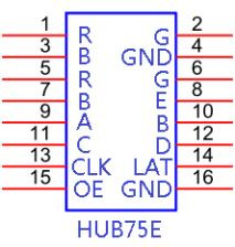
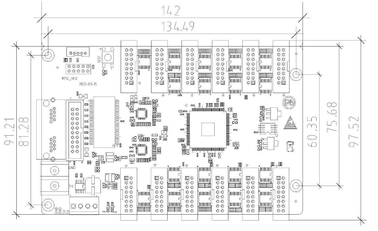
| Port | 5V DC Power*2,1Gbps Ethernet port*2, HUB75E*8 |
| Input voltage | 4V-6V |
| Power | 5W |
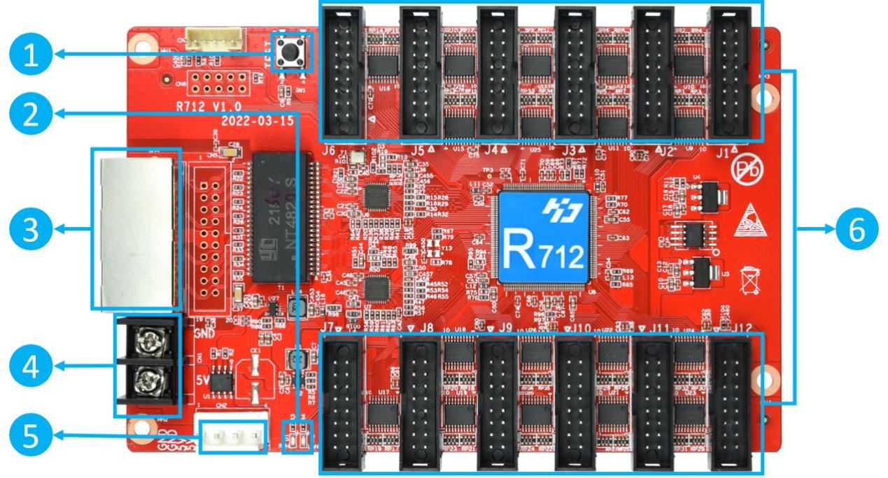 1:Test button, used to test display brightness uniformity and display module flatness. 2:Work indicator, D1 flashes to indicate that the control card is running normally. D2 flashes quickly to indicate that Gigabit has been recognized and data is being received. 3:Gigabit Ethernet port, used to connect the sending card or receiving card, the same two network ports are interchangeable. 4:Power interface, can be accessed with 4.0V ~ 5.5V DC voltage. 5:Power interface, can be accessed with 4.0V ~ 5.5V DC voltage. 6:HUB75Eport, connect to the LED modules
| Minimum | Typical | Maximum | |
| Rated voltage(V) | 4.0 | 5.0 | 5.5 |
| Storage temperature(℃) | -40 | 25 | 105 |
| Work environment temperature(℃) | -40 | 25 | 80 |
| Work environmenthumidity (%) | 0.0 | 30 | 95 |
| Net weight (kg) | 91 | ||
| Certificate | CE, FCC, RoHS | ||