All product pictures shown in this document are for illustration purpose only. Actual product may vary.
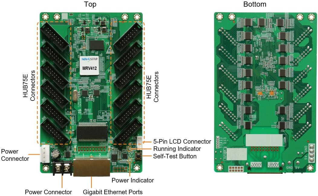
| Name | Description |
| HUB75E Connectors | Connect to the module. |
| Power Connector | Connect to the input power. Either of the connectors can be chosen. |
| Gigabit Ethernet Ports | Connect to the sending card, and cascade other receiving cards. Each connector can be used as input or output. |
| Self-Test Button | Set the test pattern.After the Ethernet cable is disconnected, press the button twice, and the test pattern will be displayed on the screen. Press the button again to switch the pattern. |
| 5-Pin LCD Connector | Connect to the LCD. |
| Indicator | Color | Status | Description |
| Running indicator | Green | Flashing once every 1s | The receiving card is functioning normally. Ethernet cable connection is normal, and video source input is available. |
| Flashing once every 3s | Ethernet cable connection is abnormal. | ||
| Flashing 3 times every 0.5s | Ethernet cable connection is normal, but no video source input is available. | ||
| Flashing once every 0.2s | The receiving card failed to load the program in the application area and is now using the backup program. | ||
| Flashing 8 times every 0.5s | A redundancy switchover occurred on the Ethernet port and the loop backup has taken effect. | ||
| Power indicator | Red | Always on | The power input is normal. |
⬤Bite error detection The Ethernet port communication quality of the receiving card can be monitored and the number of erroneous packets can be recorded to help troubleshoot network communication problems. NovaLCT V5.2.0 or later is required. ⬤Firmware program readback The receiving card firmware program can be read back and saved to the local computer. NovaLCT V5.2.0 or later is required. ⬤Configuration parameter readback The receiving card configuration parameters can be read back and saved to the local compute⬤Loop backup The receiving card and sending card form a loop via the main and backup line connections. If a fault occurs at a location of the lines, the screen can still display the image normally. ⬤Dual backup of configuration parameters The receiving card configuration parameters are stored in the application area and factory area of the receiving card at the same time. Users usually use the configuration parameters in theapplication area. If necessary, users can restore the configuration parameters in the factory area to the application area.
⬤Dual program backup
Two copies of firmware program are stored in the application area of the receiving card at the factory to avoid the problem that the receiving card may get stuck abnormally during program update.| Maximum Resolution | 512×512@60Hz | |
| Electrical Specifications | Input voltage | DC 3.8 V to 5.5 V |
| Rated current | 0.5 A | |
| Rated power consumption | 2.5 W | |
| Operating Environment | Temperature | –20°C to +70°C |
| Humidity | 10% RH to 90% RH, non-condensing | |
| Storage Environment | Temperature | –25°C to +125°C |
| Humidity | 0% RH to 95% RH, non-condensing | |
| Physical Specifications | Dimensions | 145.7 mm × 91.5 mm × 18.4 mm |
| Net weight | 93.1 g Note: It is the weight of a single receiving card only. | |
| Packing Information | Packing specifications | Each receiving card is packaged in a blister pack. Each packing box contains 100 receiving cards. |
| Packing box dimensions | 625.0 mm × 180.0 mm × 470.0 mm | |
| Name | Color | Status | Description |
| PWR | Red | Staying on | The power supply is working properly. |
| SYS | Green | Flashing once every 2s | The TB60 is functioning normally. |
| Flashing once every second | The TB60 is installing the upgrade package. | ||
| Flashing once every 0.5s | The TB60 is downloading data from the Internet or copying the upgrade package. | ||
| Staying on/off | The TB60 is abnormal. | ||
| CLOUD | Green | Staying on | The TB60 is connected to the Internet and theconnection is available. |
| Flashing once every 2s | The TB60 is connected to VNNOX and the connection is available. | ||
| RUN | Green | Flashing once every second | No video signal |
| Flashing once every 0.5s | The TB60 is functioning normally. | ||
| Staying on/off | FPGA loading is abnormal. |
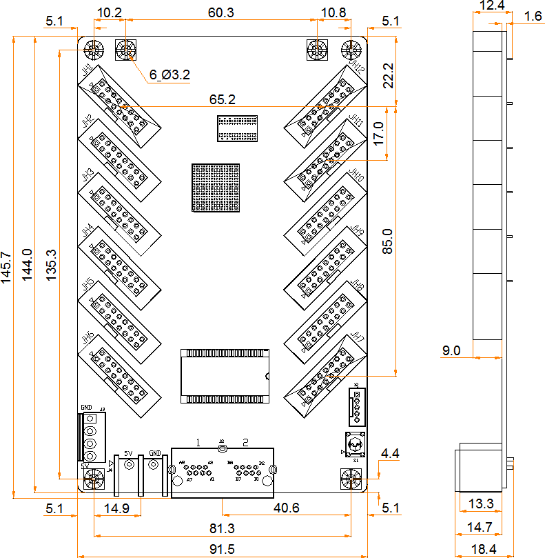
 The board thickness is not greater than 2.0 mm, and the total thickness (board thickness + thickness of components on the top and bottom sides) is not greater than 19.0 mm. Ground connection (GND) is enabled for mounting holes.To make molds or trepan mounting holes, please contact NovaStar for a higher-precision structural drawing.
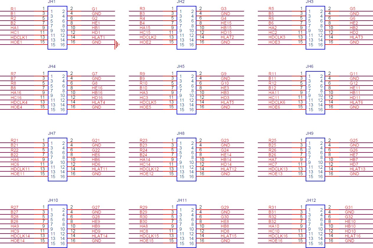
| Pin Definitions (Take JH1 as an example) | |||||
| / | R1 | 1 | 2 | G1 | / |
| / | B1 | 3 | 4 | GND | Ground |
| / | R2 | 5 | 6 | G2 | / |
| / | B2 | 7 | 8 | HE1 | Line decoding signal |
| Line decoding signal | HA1 | 9 | 10 | HB1 | Line decoding signal |
| Line decoding signal | HC1 | 11 | 12 | HD1 | Line decoding signal |
| Shift clock | HDCLK1 | 13 | 14 | HLAT1 | Latch signal |
| Display enable signal | HOE1 | 15 | 16 | GND | Ground |
